
Introduction to Networking
The TCP/IP Five-Layer Network Model
Section titled “The TCP/IP Five-Layer Network Model”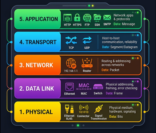
Every network communication passes through a stack of layers. Each layer has a specific job, and each layer only talks to the layers directly above and below it.
| Layer | Name | Protocol Examples | What it does |
|---|---|---|---|
| 5 | Application | HTTP, FTP, SMTP, DNS, SSH | User-facing data exchange - what apps actually send/receive |
| 4 | Transport | TCP, UDP | Reliable (TCP) or fast (UDP) delivery to the right application via ports |
| 3 | Network | IP (IPv4/IPv6) | Routing across networks - getting data from network A to network B |
| 2 | Data Link | Ethernet, Wi-Fi (802.11) | Getting data across a single link/segment - MAC addressing |
| 1 | Physical | Cables, radio waves, fiber | Moving raw bits (1s and 0s) across a wire, fiber, or air |
The Delivery Truck Analogy
Section titled “The Delivery Truck Analogy”Think of sending a package:
- Physical layer = the delivery truck and the roads
- Data link layer = how the truck gets from one intersection to the next
- Network layer = which roads to take from address A to address B
- Transport layer = the driver knowing how to knock on your door to confirm delivery
- Application layer = the contents of the package itself
Networking Hardware
Section titled “Networking Hardware”Cables
Section titled “Cables”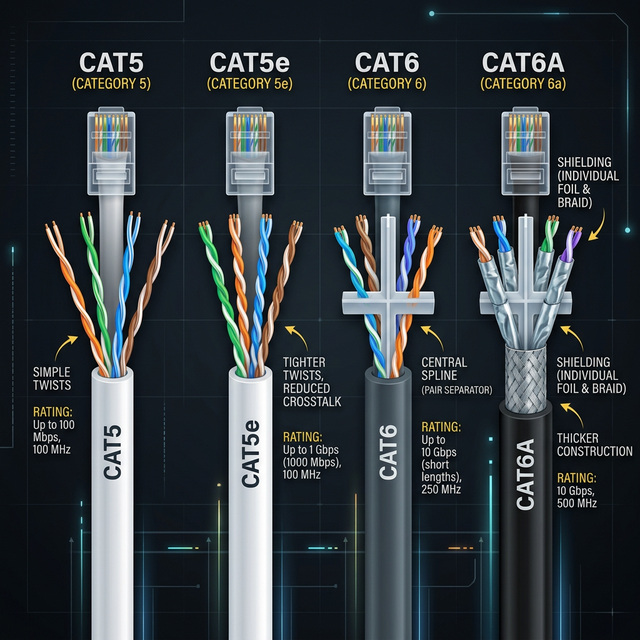
The physical medium that carries data. Two main categories:
| Type | Medium | Speed | Distance | Use Case |
|---|---|---|---|---|
| Cat5 | Copper twisted pair | 100 Mbps | 100m | Legacy (avoid for new installs) |
| Cat5e | Copper twisted pair | 1 Gbps | 100m | Common in existing installs |
| Cat6 | Copper twisted pair | 10 Gbps (up to 55m) | 100m at 1G | Standard for new installs |
| Cat6a | Copper twisted pair | 10 Gbps | 100m | Data centers, PoE applications |
| Fiber (single-mode) | Glass (light pulses) | 100+ Gbps | Up to 80km | Long distance / WAN links |
| Fiber (multi-mode) | Glass (light pulses) | 10-100 Gbps | Up to 2km | Data center interconnects |
Key concepts:
- Crosstalk - electrical signal on one wire bleeds onto an adjacent wire. Twisting the pairs together reduces this.
- Copper uses electrical voltages to represent 1s and 0s
- Fiber uses pulses of light - faster, longer range, immune to electromagnetic interference, but more expensive and fragile
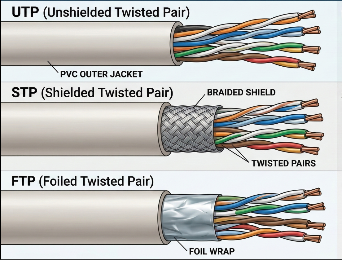
Twisted pair cable types:
| Type | Shielding | Cost | Use Case |
|---|---|---|---|
| UTP (Unshielded) | None - just the twist | Lowest | Home, office (most common) |
| STP (Shielded) | Braided metal shield around all pairs | Medium | Environments with EMI |
| FTP (Foiled) | Foil wrap around all pairs | Medium | Similar to STP |
Network Ports and Connections
Section titled “Network Ports and Connections”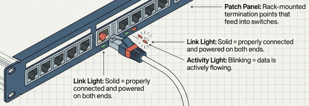
- RJ-45 is the standard plug/socket for twisted pair Ethernet
- Link light (on the port) = cable properly connected and both ends powered
- Activity light (on the port) = data is actively flowing
- Patch panel = a rack-mounted panel of RJ-45 ports where cable runs terminate. Cables from the panel then connect to switches.
# Check link status on Linuxip link show# eth0: <BROADCAST,MULTICAST,UP,LOWER_UP> ...#   ^^ UP = interface enabled, LOWER_UP = cable connected
# Detailed interface info (speed, duplex, link status)ethtool eth0# Speed: 1000Mb/s# Duplex: Full# Link detected: yes
Hubs, Switches, and Routers
Section titled “Hubs, Switches, and Routers”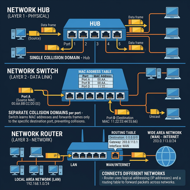
These three devices form the hierarchy of network infrastructure:
| Device | OSI Layer | Intelligence | How it forwards |
|---|---|---|---|
| Hub | Layer 1 (Physical) | None | Broadcasts everything to all ports - every device sees every frame |
| Switch | Layer 2 (Data Link) | Reads MAC addresses | Forwards frames only to the port where the destination MAC lives |
| Router | Layer 3 (Network) | Reads IP addresses | Forwards packets between different networks based on routing tables |
Hub - a “dumb repeater.” All ports share a single collision domain. If two devices send simultaneously, signals collide and both must retry after a random backoff. Hubs are obsolete.
Switch - inspects Ethernet frames, reads the destination MAC address, and forwards only to the correct port. Eliminates collision domains (each port is its own collision domain). This is why switches replaced hubs everywhere.
Router - connects separate networks (your LAN to the internet, office A to office B). Routers inspect IP headers to decide where to forward. They maintain routing tables and share route information with other routers via BGP (Border Gateway Protocol).
Servers and Clients
Section titled “Servers and Clients”- A server provides data to something requesting it
- A client requests data from a server
- The same device can be both: an email server is a client of a DNS server
- Most devices are primarily one role but play both at different times
The Physical Layer
Section titled “The Physical Layer”The physical layer’s job: move 1s and 0s from one end of a link to the other. Nothing more.
How Bits Travel
Section titled “How Bits Travel”- Bit = the smallest unit of data (a 1 or a 0)
- On copper cables, bits are encoded as electrical voltage changes - a process called modulation (or more specifically, line coding)
- On fiber cables, bits are encoded as pulses of light
- On wireless links, bits are encoded as radio wave modulations
Duplex Communication
Section titled “Duplex Communication”Twisted pair cables have multiple wire pairs, which enables simultaneous two-way communication:
| Mode | Direction | Description |
|---|---|---|
| Simplex | One way only | Like a loudspeaker - data flows in one direction |
| Half-duplex | Both ways, but not simultaneously | Like a walkie-talkie - one side at a time |
| Full-duplex | Both ways simultaneously | Like a phone call - both sides talk at once |
Modern Ethernet runs full-duplex by default. Dedicated wire pairs handle each direction. If you see a link reporting half-duplex, something is wrong (duplex mismatch, bad cable, or a hub in the path).
# Check duplex modeethtool eth0 | grep -i duplex# Duplex: Full
# If you see half-duplex on a modern gigabit link, investigate:# - Cable problem? (check with cable tester)# - Duplex mismatch? (both ends should auto-negotiate)# - Hub in the path? (replace with a switch)
The Data Link Layer
Section titled “The Data Link Layer”The data link layer solves the problem: multiple devices share the same physical medium - how do we avoid chaos?
Ethernet and CSMA/CD
Section titled “Ethernet and CSMA/CD”Ethernet is the dominant data link protocol. It solved the collision problem with CSMA/CD (Carrier Sense Multiple Access with Collision Detection):
- Listen before sending - if the wire is quiet, go ahead and transmit
- If a collision is detected - both devices stop transmitting immediately
- Random backoff - each device waits a random interval before retrying (prevents repeated collisions)
MAC Addresses
Section titled “MAC Addresses”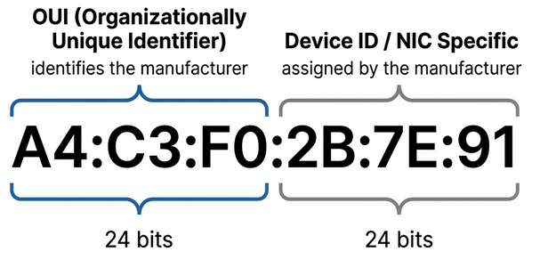
A MAC address (Media Access Control) is a 48-bit hardware address burned into every network interface. It’s globally unique.
A4:C3:F0:2B:7E:91── ── ── ── ── ── \__OUI__/ \__Device__/
First 3 octets = OUI (Organizationally Unique Identifier) Assigned to the manufacturer by IEEELast 3 octets = Device ID (assigned by manufacturer, unique per NIC)# View your MAC addressip link show eth0# link/ether a4:c3:f0:2b:7e:91 brd ff:ff:ff:ff:ff:ff
# Look up a MAC address OUI (manufacturer)# First 3 octets identify the vendor# https://maclookup.app/ or:curl -s "https://api.maclookup.app/v2/macs/A4C3F0" | python3 -m json.toolUnicast, Multicast, and Broadcast
Section titled “Unicast, Multicast, and Broadcast”| Type | Destination | Who receives it |
|---|---|---|
| Unicast | One specific MAC address | Only the target device |
| Multicast | A group MAC address | All devices in the multicast group |
| Broadcast | FF:FF:FF:FF:FF:FF | Every device on the LAN segment |
The least significant bit of the first octet determines the type:
- Bit = 0 -> unicast (destined for a single device)
- Bit = 1 -> multicast (destined for a group)
Ethernet Frame Structure
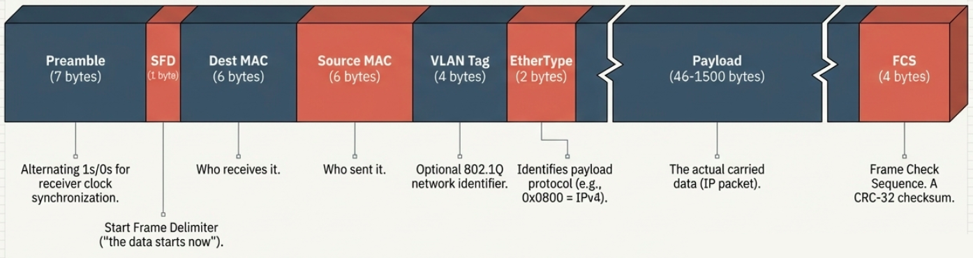
Section titled “Ethernet Frame Structure”Every piece of data on an Ethernet network is wrapped in a frame with this structure:
| Field | Size | Purpose |
|---|---|---|
| Preamble | 7 bytes | Alternating 1s and 0s - lets the receiver sync its clock |
| SFD (Start Frame Delimiter) | 1 byte | Signals: “the actual frame data starts now” |
| Destination MAC | 6 bytes | Who should receive this frame |
| Source MAC | 6 bytes | Who sent this frame |
| VLAN tag (optional) | 4 bytes | Identifies which VLAN the frame belongs to (802.1Q) |
| EtherType | 2 bytes | What protocol is in the payload (e.g., 0x0800 = IPv4, 0x86DD = IPv6) |
| Payload | 46-1500 bytes | The actual data (IP packet, ARP request, etc.) |
| FCS (Frame Check Sequence) | 4 bytes | CRC-32 checksum for error detection |
VLANs - Virtual LANs
Section titled “VLANs - Virtual LANs”A VLAN lets you create multiple logical networks on the same physical switch. Devices on VLAN 10 can’t see traffic on VLAN 20, even if they’re plugged into the same switch.
- 802.1Q tag is inserted into the Ethernet frame header (4 bytes) to identify which VLAN a frame belongs to
- Traffic between VLANs requires a router (inter-VLAN routing)
- Common use: separate guest Wi-Fi (VLAN 100) from corporate network (VLAN 10) on the same physical infrastructure
# Check VLAN configuration on Linuxip -d link show
# Create a VLAN interfacesudo ip link add link eth0 name eth0.10 type vlan id 10sudo ip addr add 192.168.10.1/24 dev eth0.10sudo ip link set eth0.10 up
# View VLAN membership on a managed switch (varies by vendor)# Cisco: show vlan brief# Linux bridge: bridge vlan show
How a Frame Travels Through the Network
Section titled “How a Frame Travels Through the Network”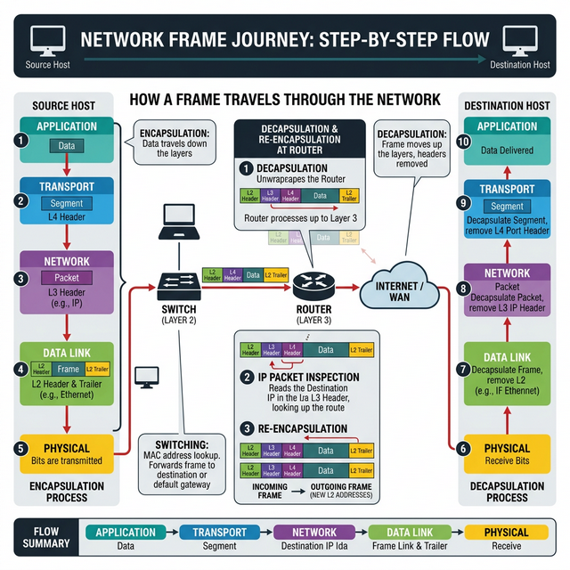
Putting it all together - when you browse example.com:
- Application layer generates an HTTP request
- Transport layer wraps it in a TCP segment (adds port numbers)
- Network layer wraps it in an IP packet (adds source/destination IP)
- Data link layer wraps it in an Ethernet frame (adds source/destination MAC)
- Physical layer converts the frame to electrical signals and pushes it onto the wire
- At each router hop, the Ethernet frame is unwrapped and rewrapped with new MAC addresses, but the IP packet inside stays the same until it reaches the destination network