The Network Layer
IPv4 Addressing
Section titled “IPv4 Addressing”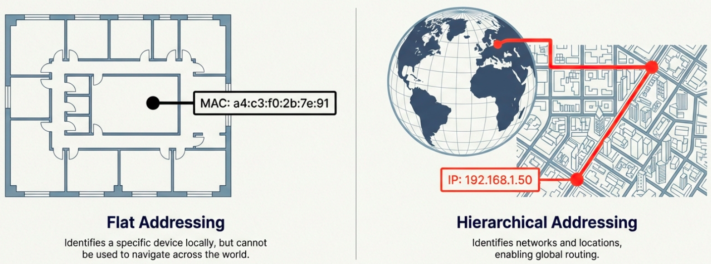
On a LAN, devices communicate using MAC addresses (Layer 2). But MAC addresses are flat - they aren’t hierarchical and can’t be used for routing across networks. IP addresses solve this.
IPv4 Address Format
Section titled “IPv4 Address Format”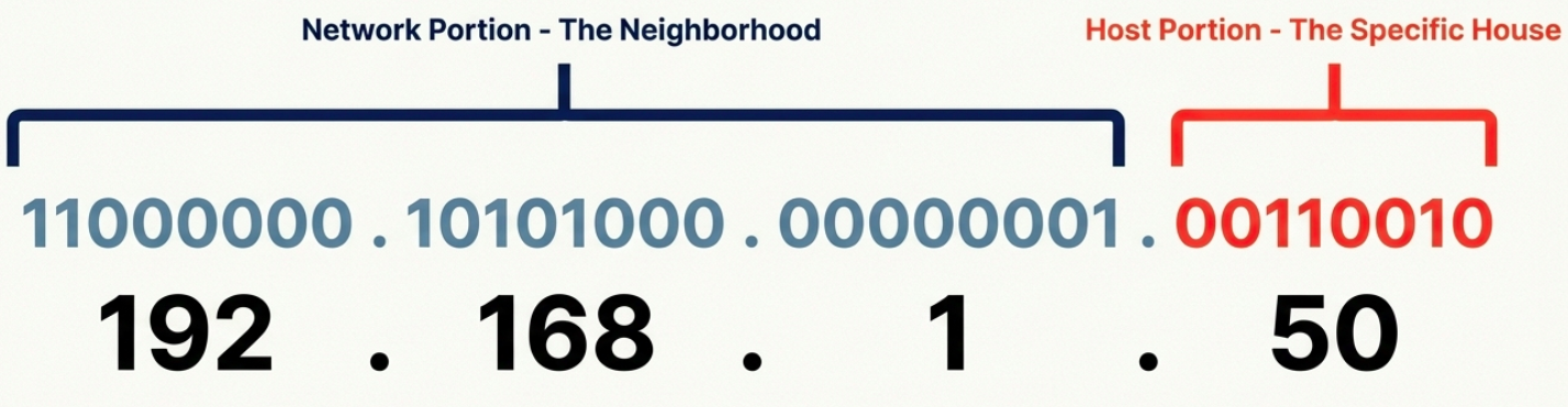
An IPv4 address is a 32-bit number written as four octets in dotted decimal notation:
192.168.1.100 │    │  │  │ 8   8  8  8  bits = 32 bits total
Each octet = 8 bits = 0 to 255- IP addresses belong to networks, not devices. A laptop gets a new IP when it joins a new network.
- Dynamic IP (via DHCP) - automatically assigned, common for clients
- Static IP - manually configured, used for servers and network equipment
IPv4 Datagram Structure
Section titled “IPv4 Datagram Structure”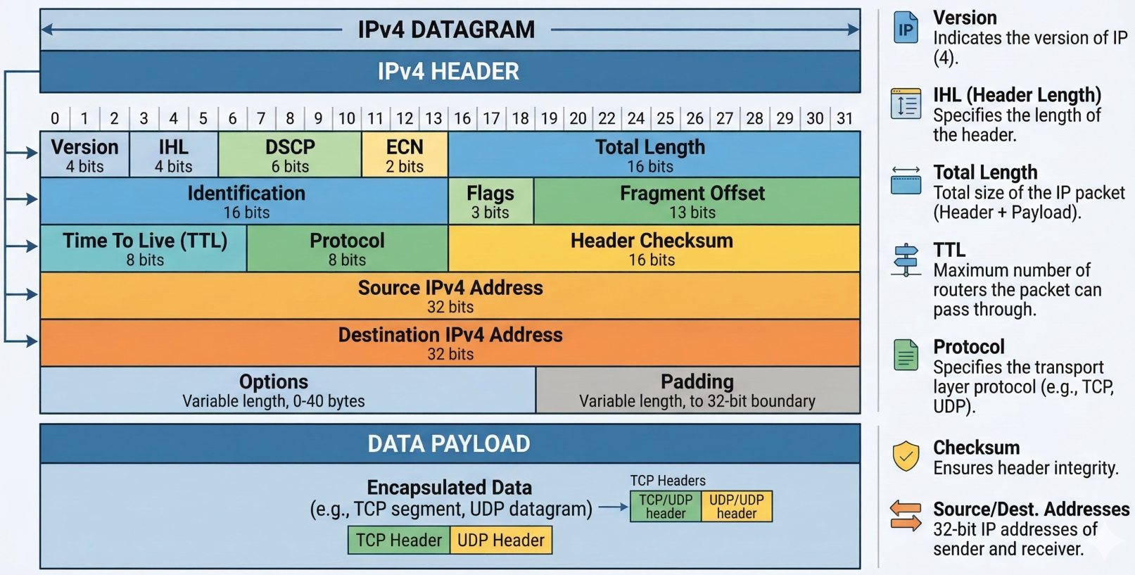
Every IP packet (called a datagram) has a header with these fields:
| Field | Size | Purpose |
|---|---|---|
| Version | 4 bits | IP version (4 for IPv4) |
| Header Length (IHL) | 4 bits | Header size (usually 20 bytes / 5 words) |
| Type of Service (DSCP) | 8 bits | Quality of Service (QoS) priority marking |
| Total Length | 16 bits | Entire datagram size (max 65,535 bytes) |
| Identification | 16 bits | Groups fragments of the same original datagram |
| Flags | 3 bits | Controls fragmentation (DF = Don’t Fragment, MF = More Fragments) |
| Fragment Offset | 13 bits | Position of this fragment in the original datagram |
| TTL (Time to Live) | 8 bits | Hop counter - decremented at each router, dropped at 0 |
| Protocol | 8 bits | Upper-layer protocol (6=TCP, 17=UDP, 1=ICMP) |
| Header Checksum | 16 bits | Error detection for the header only |
| Source IP | 32 bits | Sender’s IP address |
| Destination IP | 32 bits | Recipient’s IP address |
| Options | Variable | Optional - used for testing/debugging (rarely used) |
| Padding | Variable | Zeros to ensure header aligns to 32-bit boundary |
Fragmentation occurs when a datagram exceeds the MTU (Maximum Transmission Unit) of a link (typically 1500 bytes for Ethernet). The IP layer splits it into smaller fragments, each with the same Identification field. The receiving host reassembles them.
# Check the MTU of an interfaceip link show eth0 | grep mtu# mtu 1500
# Test path MTU to a destination (avoid fragmentation issues)ping -c 4 -s 1472 -M do 8.8.8.8# -s 1472 + 28 bytes overhead = 1500 (exact MTU)# If fragmentation needed, you'll get an ICMP error
IPv4 Address Classes (Historical)
Section titled “IPv4 Address Classes (Historical)”Before CIDR, IP addresses were divided into classes based on the first few bits:
| Class | First Bits | Network / Host Split | Range | Hosts per Network | Use |
|---|---|---|---|---|---|
| A | 0 | 8 / 24 | 0.0.0.0 - 127.255.255.255 | 16,777,214 | Large ISPs, governments |
| B | 10 | 16 / 16 | 128.0.0.0 - 191.255.255.255 | 65,534 | Medium-large organizations |
| C | 110 | 24 / 8 | 192.0.0.0 - 223.255.255.255 | 254 | Small networks |
| D | 1110 | N/A | 224.0.0.0 - 239.255.255.255 | N/A | Multicast |
| E | 1111 | N/A | 240.0.0.0 - 255.255.255.255 | N/A | Reserved / experimental |
ARP - Address Resolution Protocol
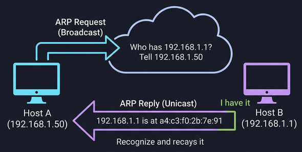
Section titled “ARP - Address Resolution Protocol”ARP bridges Layer 2 and Layer 3. When a device knows the destination IP (Layer 3) but not the MAC address (Layer 2), it uses ARP to find it.
How ARP works:
- Device broadcasts an ARP request: “Who has IP
192.168.1.1? Tell192.168.1.50” - The device with that IP responds with an ARP reply: “I’m
192.168.1.1, my MAC isa4:c3:f0:2b:7e:91” - The requesting device caches this in its ARP table (entries expire after a timeout to account for network changes)
# View the ARP tableip neigh show# or the legacy command:arp -a
# Manually add a static ARP entry (rarely needed)sudo ip neigh add 192.168.1.1 lladdr aa:bb:cc:dd:ee:ff dev eth0
# Clear the ARP cachesudo ip neigh flush all
# On Windowsarp -aSubnetting
Section titled “Subnetting”Why Subnets?
Section titled “Why Subnets?”Before modern routing, IPs were handed out in rigid classes (A,B,C). It was massively wasteful; a company needing 300 addresses would get a Class B with 65,534 hosts, wasting over 65,000 addresses. Subnetting solves this by splitting a large network into smaller, manageable pieces, each with its own gateway router.
Internet │ Core Router ┌────┼────┐ │ │ │ Subnet Subnet Subnet /26 /26 /26 (62) (62) (62) hosts eachSubnet Masks
Section titled “Subnet Masks”A subnet mask is a 32-bit number that tells you where the network/subnet portion ends and the host portion begins:
| Subnet Mask | Binary | CIDR | Network Bits | Host Bits | Usable Hosts |
|---|---|---|---|---|---|
255.0.0.0 | 11111111.00000000.00000000.00000000 | /8 | 8 | 24 | 16,777,214 |
255.255.0.0 | 11111111.11111111.00000000.00000000 | /16 | 16 | 16 | 65,534 |
255.255.255.0 | 11111111.11111111.11111111.00000000 | /24 | 24 | 8 | 254 |
255.255.255.128 | 11111111.11111111.11111111.10000000 | /25 | 25 | 7 | 126 |
255.255.255.192 | 11111111.11111111.11111111.11000000 | /26 | 26 | 6 | 62 |
255.255.255.224 | 11111111.11111111.11111111.11100000 | /27 | 27 | 5 | 30 |
255.255.255.240 | 11111111.11111111.11111111.11110000 | /28 | 28 | 4 | 14 |
255.255.255.252 | 11111111.11111111.11111111.11111100 | /30 | 30 | 2 | 2 |
Calculating Subnets
Section titled “Calculating Subnets”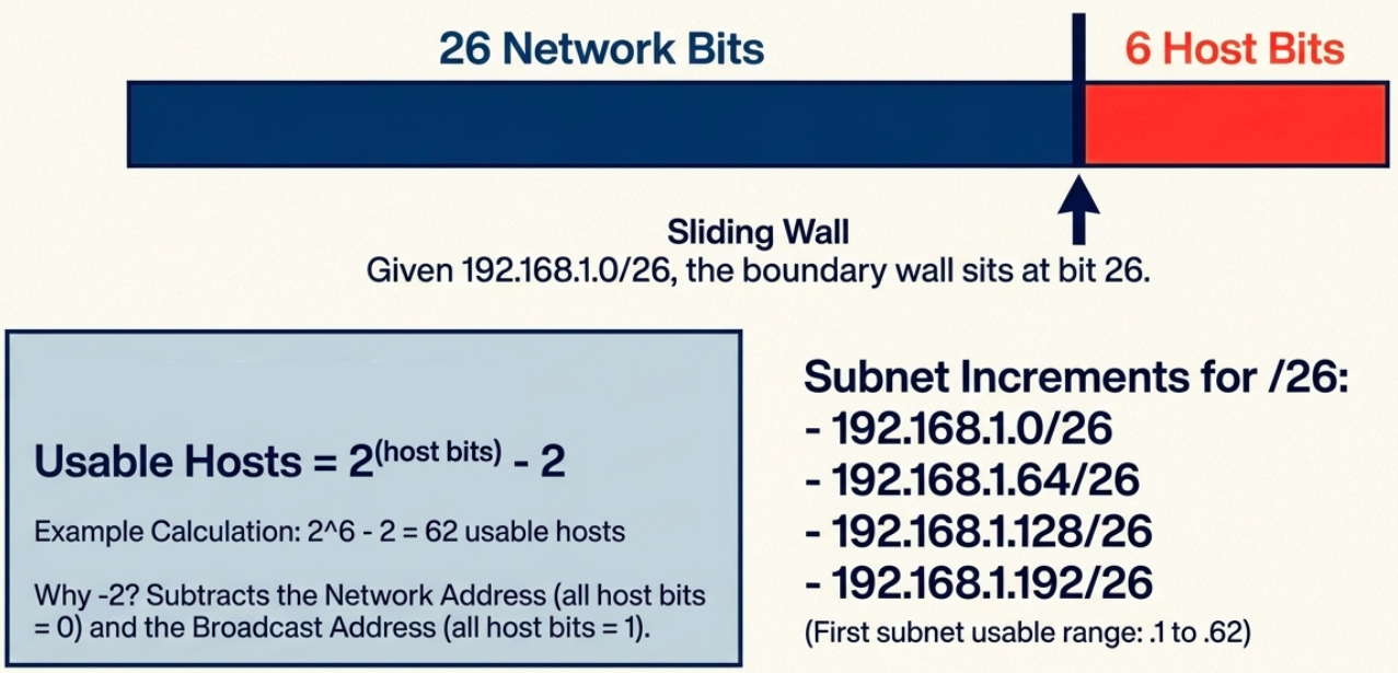
Given 192.168.1.0/26:
- Network bits = 26, Host bits = 6
- Subnet increment = 2^6 = 64
- Subnets:
192.168.1.0/26,192.168.1.64/26,192.168.1.128/26,192.168.1.192/26 - First subnet usable range:
192.168.1.1to192.168.1.62(broadcast:192.168.1.63)
# Quick subnet calculation with ipcalcipcalc 192.168.1.0/26# Network:   192.168.1.0/26# Netmask:   255.255.255.192 = 26# Wildcard:  0.0.0.63# HostMin:   192.168.1.1# HostMax:   192.168.1.62# Broadcast: 192.168.1.63# Hosts/Net: 62
# View your subnet informationip addr show eth0# inet 192.168.1.50/24 brd 192.168.1.255 scope global eth0
CIDR - Classless Inter-Domain Routing
Section titled “CIDR - Classless Inter-Domain Routing”The Problem CIDR Solves
Section titled “The Problem CIDR Solves”Classful addressing was wasteful. A company needing 300 IPs couldn’t use a /24 (254 hosts) and had to request a /16 (65,534 hosts) - wasting 65,000+ addresses. CIDR removed the fixed class boundaries.
How CIDR Works
Section titled “How CIDR Works”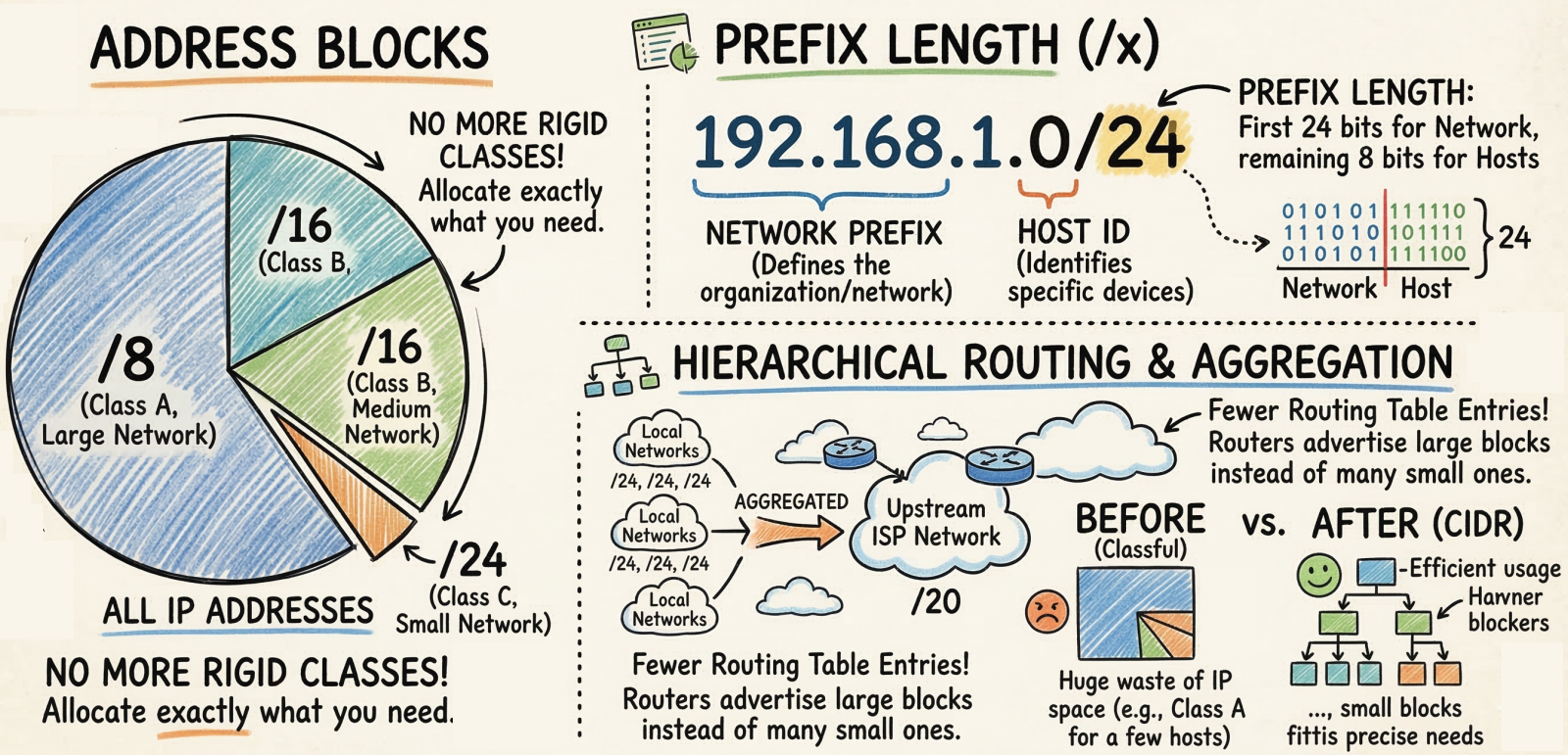
CIDR uses Variable Length Subnet Masking (VLSM) - the network/host boundary can be placed anywhere in the 32 bits, not just at the 8/16/24-bit boundaries.
Classful:  Class A = /8  Class B = /16      Only 3 options  Class C = /24
CIDR:  /1, /2, /3 ... /30, /31, /32    Any prefix length
Key benefits:
- No address waste - allocate exactly the number of IPs needed (e.g., /27 for 30 hosts)
- Route aggregation (supernetting) - combine multiple networks into one route entry (e.g., two /24s become one /23), shrinking routing tables
- Flexible network design - networks can be any size, not just A/B/C
CIDR Quick Reference
Section titled “CIDR Quick Reference”| CIDR | Subnet Mask | Total IPs | Usable Hosts |
|---|---|---|---|
| /8 | 255.0.0.0 | 16,777,216 | 16,777,214 |
| /16 | 255.255.0.0 | 65,536 | 65,534 |
| /20 | 255.255.240.0 | 4,096 | 4,094 |
| /24 | 255.255.255.0 | 256 | 254 |
| /25 | 255.255.255.128 | 128 | 126 |
| /26 | 255.255.255.192 | 64 | 62 |
| /27 | 255.255.255.224 | 32 | 30 |
| /28 | 255.255.255.240 | 16 | 14 |
| /30 | 255.255.255.252 | 4 | 2 |
| /32 | 255.255.255.255 | 1 | 1 |
Routing
Section titled “Routing”How Routing Works
Section titled “How Routing Works”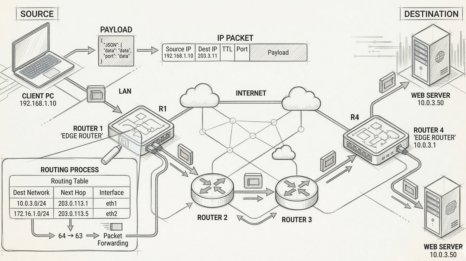
A router sits between networks and decides where to forward each packet based on its destination IP:
- Packet arrives on one interface
- Router reads the destination IP from the IP header
- Router looks up the destination in its routing table
- Router forwards the packet out the interface closest to the destination
The Routing Table
Section titled “The Routing Table”Every router maintains a routing table with these core columns:
| Column | What it contains |
|---|---|
| Destination Network | Network ID + subnet mask (CIDR notation) |
| Next Hop | IP of the next router to forward to (or “directly connected”) |
| Metric | Cost/distance of this route (lower = preferred) |
| Interface | Which of the router’s interfaces to send the packet out of |
# View the routing table on Linuxip route show# default via 192.168.1.1 dev eth0 proto dhcp metric 100# 192.168.1.0/24 dev eth0 proto kernel scope link src 192.168.1.50
# Add a static routesudo ip route add 10.0.0.0/8 via 192.168.1.254
# Windowsroute print
Routing Protocols
Section titled “Routing Protocols”Routers don’t know about every network by default - they learn routes dynamically by talking to neighboring routers using routing protocols.
Interior Gateway Protocols (IGP) - Within an Autonomous System
Section titled “Interior Gateway Protocols (IGP) - Within an Autonomous System”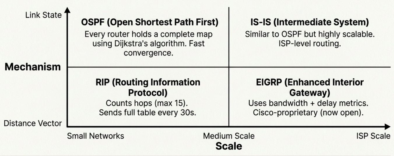
| Protocol | Type | How it works | Scale |
|---|---|---|---|
| RIP (Routing Information Protocol) | Distance vector | Counts hops (max 15). Sends full routing table to neighbors every 30s. | Small networks (fewer than 100 routers) |
| EIGRP (Enhanced Interior Gateway) | Advanced distance vector | Uses bandwidth + delay as metrics. Cisco-proprietary (now open). | Medium networks |
| OSPF (Open Shortest Path First) | Link state | Every router has a complete map of the network. Uses Dijkstra’s algorithm. | Large enterprise networks |
| IS-IS (Intermediate System) | Link state | Similar to OSPF. Used by ISPs and very large networks. | ISP-scale networks |
Distance vector protocols are simpler but slower to converge. Routers only know what their neighbors tell them (“I can reach 10.0.0.0 in 3 hops”).
Link state protocols are more complex but converge faster. Every router has the full topology map and independently calculates the best path.
Exterior Gateway Protocol (EGP) - Between Autonomous Systems
Section titled “Exterior Gateway Protocol (EGP) - Between Autonomous Systems”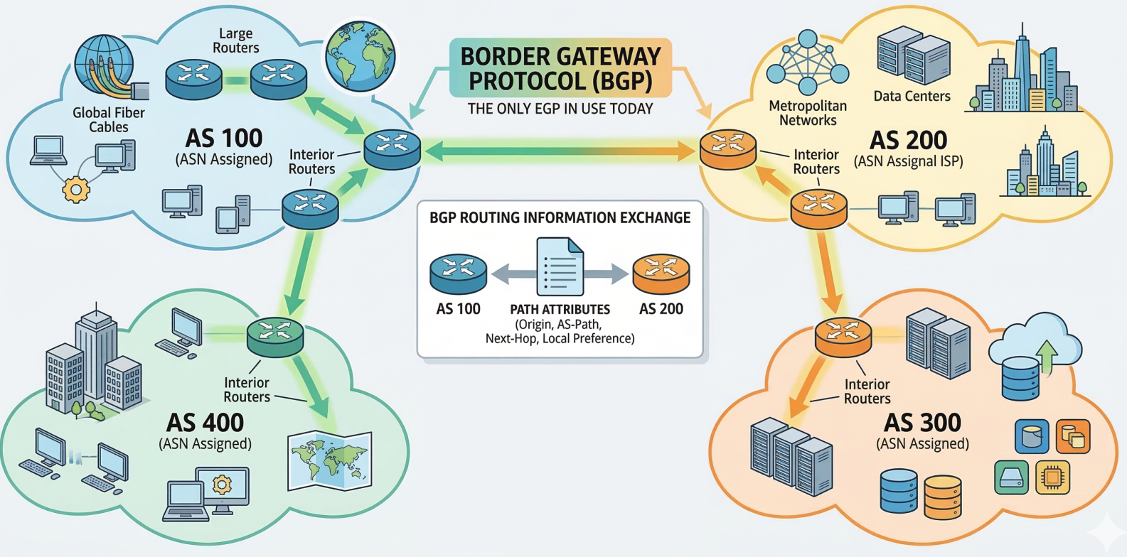
BGP (Border Gateway Protocol) is the only EGP in use today. It’s the protocol that makes the internet work - every ISP, cloud provider, and large organization uses BGP to exchange routing information.
- An Autonomous System (AS) is a collection of networks under one administrative entity
- Each AS gets an ASN (Autonomous System Number) assigned by IANA/regional registries
- BGP routers exchange path attributes to determine the best route across the internet
Non-Routable (Private) Address Space
Section titled “Non-Routable (Private) Address Space”RFC 1918 reserves three IP ranges for private/internal use. These IPs are never routed on the public internet - IGPs route them internally, but EGPs (BGP) reject them.
| Range | CIDR | Total IPs | Typical Use |
|---|---|---|---|
10.0.0.0 - 10.255.255.255 | 10.0.0.0/8 | 16.7 million | Large enterprise networks, cloud VPCs |
172.16.0.0 - 172.31.255.255 | 172.16.0.0/12 | ~1 million | Medium organizations, Docker default |
192.168.0.0 - 192.168.255.255 | 192.168.0.0/16 | 65,536 | Home networks, small offices |
Devices on private IPs reach the internet through NAT (Network Address Translation), which rewrites the private source IP to the router’s public IP on outgoing packets.
| Routable (Public) IPs | Non-Routable (Private) IPs |
|---|---|
| Forwarded between networks by routers | Not forwarded beyond the local network |
| Globally unique, assigned by RIRs | Can be reused in any private network |
| Directly accessible from the internet | Requires NAT for internet access |
| Needs firewall protection | Inherently isolated from the internet |
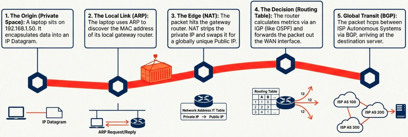
Synthesis: The Complete Path
Section titled “Synthesis: The Complete Path”Layer 3 is an elegant choreography of local discovery, private isolation, and global routing.