
Introduction to Networking
The TCP/IP Five-Layer Network Model
Section titled “The TCP/IP Five-Layer Network Model”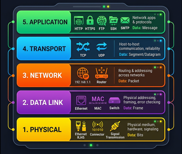
Every network communication passes through a stack of layers. Each layer has a specific job, and each layer only talks to the layers directly above and below it.
| Layer | Name | Protocol Examples | What it does |
|---|---|---|---|
| 5 | Application | HTTP, FTP, SMTP, DNS, SSH | User-facing data exchange - what apps actually send/receive |
| 4 | Transport | TCP, UDP | Reliable (TCP) or fast (UDP) delivery to the right application via ports |
| 3 | Network | IP (IPv4/IPv6) | Routing across networks - getting data from network A to network B |
| 2 | Data Link | Ethernet, Wi-Fi (802.11) | Getting data across a single link/segment - MAC addressing |
| 1 | Physical | Cables, radio waves, fiber | Moving raw bits (1s and 0s) across a wire, fiber, or air |
The Delivery Truck Analogy
Section titled “The Delivery Truck Analogy”Think of sending a package (for a full worked example across all five layers, see A web request, end to end):
- Physical layer = the delivery truck and the roads
- Data link layer = how the truck gets from one intersection to the next
- Network layer = which roads to take from address A to address B
- Transport layer = the driver knowing how to knock on your door to confirm delivery
- Application layer = the contents of the package itself
Protocols and standards
Section titled “Protocols and standards”Each layer works because both ends follow the same protocol: the message formats, their order, and what each side does on receipt. The IETF publishes internet protocols as numbered RFCs, such as RFC 791 for IPv4, RFC 9293 for TCP, and RFC 9110 for HTTP semantics. The IEEE 802 committees define link-layer standards: 802.3 is Ethernet and 802.11 is Wi-Fi. When two implementations disagree, the RFC is the tiebreaker.
# Read an RFC from the terminalcurl -s https://www.rfc-editor.org/rfc/rfc9293.txt | lessNetworking Hardware
Section titled “Networking Hardware”Cables
Section titled “Cables”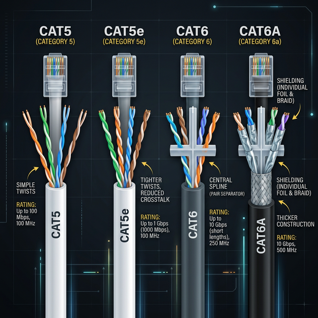
The physical medium that carries data. Two main categories:
| Type | Medium | Speed | Distance | Use Case |
|---|---|---|---|---|
| Cat5 | Copper twisted pair | 100 Mbps | 100m | Legacy (avoid for new installs) |
| Cat5e | Copper twisted pair | 1 Gbps | 100m | Common in existing installs |
| Cat6 | Copper twisted pair | 10 Gbps (up to 55m) | 100m at 1G | Standard for new installs |
| Cat6a | Copper twisted pair | 10 Gbps | 100m | Data centers, PoE applications |
| Fiber (single-mode) | Glass (light pulses) | 100+ Gbps | Up to 80km | Long distance / WAN links |
| Fiber (multi-mode) | Glass (light pulses) | 10-100 Gbps | Up to 2km | Data center interconnects |
Key concepts:
- Crosstalk - electrical signal on one wire bleeds onto an adjacent wire. Twisting the pairs together reduces this.
- Copper uses electrical voltages to represent 1s and 0s
- Fiber uses pulses of light - faster, longer range, immune to electromagnetic interference, but more expensive and fragile
Twisted pair cable types:
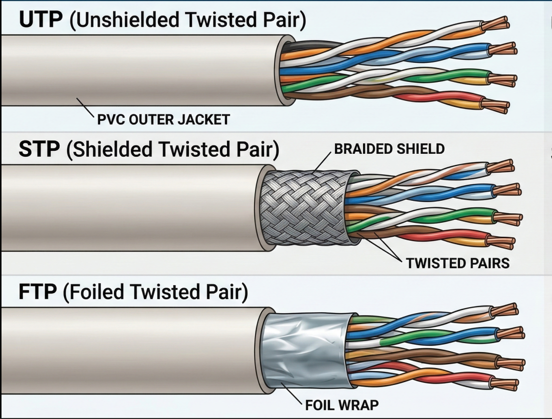
| Type | Shielding | Cost | Use Case |
|---|---|---|---|
| UTP (Unshielded) | None - just the twist | Lowest | Home, office (most common) |
| STP (Shielded) | Braided metal shield around all pairs | Medium | Environments with EMI |
| FTP (Foiled) | Foil wrap around all pairs | Medium | Similar to STP |
Network Ports and Connections
Section titled “Network Ports and Connections”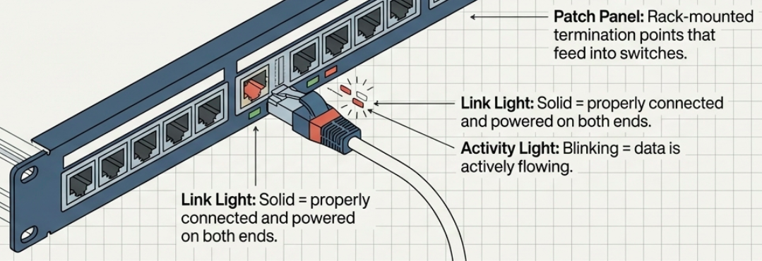
- RJ-45 is the standard plug/socket for twisted pair Ethernet
- Link light (on the port) = cable properly connected and both ends powered
- Activity light (on the port) = data is actively flowing
- Patch panel = a rack-mounted panel of RJ-45 ports where cable runs terminate. Cables from the panel then connect to switches.
# Check link status on Linuxip link show# eth0: <BROADCAST,MULTICAST,UP,LOWER_UP> ...#   ^^ UP = interface enabled, LOWER_UP = cable connected
# Detailed interface info (speed, duplex, link status)ethtool eth0# Speed: 1000Mb/s# Duplex: Full# Link detected: yes
Hubs, Switches, and Routers
Section titled “Hubs, Switches, and Routers”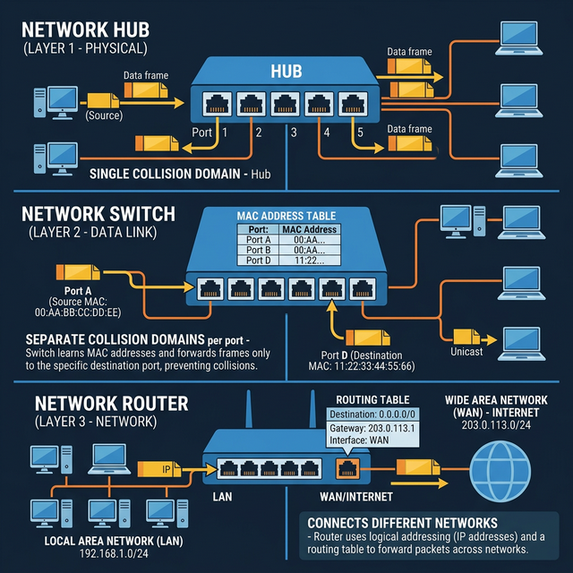
These three devices form the hierarchy of network infrastructure:
| Device | OSI Layer | Intelligence | How it forwards |
|---|---|---|---|
| Hub | Layer 1 (Physical) | None | Broadcasts everything to all ports - every device sees every frame |
| Switch | Layer 2 (Data Link) | Reads MAC addresses | Forwards frames only to the port where the destination MAC lives |
| Router | Layer 3 (Network) | Reads IP addresses | Forwards packets between different networks based on routing tables |
Hub - a “dumb repeater.” All ports share a single collision domain. If two devices send simultaneously, signals collide and both must retry after a random backoff. Hubs are obsolete.
Switch - inspects Ethernet frames, reads the destination MAC address, and forwards only to the correct port. Eliminates collision domains (each port is its own collision domain). This is why switches replaced hubs everywhere.
Router - connects separate networks (your LAN to the internet, office A to office B). Routers inspect IP headers to decide where to forward. They maintain routing tables and share route information with other routers via BGP (Border Gateway Protocol).
Servers and Clients
Section titled “Servers and Clients”- A server provides data to something requesting it
- A client requests data from a server
- The same device can be both: an email server is a client of a DNS server
- Most devices are primarily one role but play both at different times
The Physical Layer
Section titled “The Physical Layer”The physical layer’s job: move 1s and 0s from one end of a link to the other. Nothing more.
How Bits Travel
Section titled “How Bits Travel”- Bit = the smallest unit of data (a 1 or a 0)
- On copper cables, bits are encoded as electrical voltage changes - a process called modulation (or more specifically, line coding)
- On fiber cables, bits are encoded as pulses of light
- On wireless links, bits are encoded as radio wave modulations
Duplex Communication
Section titled “Duplex Communication”Twisted pair cables have multiple wire pairs, which enables simultaneous two-way communication:
| Mode | Direction | Description |
|---|---|---|
| Simplex | One way only | Like a loudspeaker - data flows in one direction |
| Half-duplex | Both ways, but not simultaneously | Like a walkie-talkie - one side at a time |
| Full-duplex | Both ways simultaneously | Like a phone call - both sides talk at once |
Modern Ethernet runs full-duplex by default. Dedicated wire pairs handle each direction. If you see a link reporting half-duplex, something is wrong (duplex mismatch, bad cable, or a hub in the path).
# Check duplex modeethtool eth0 | grep -i duplex# Duplex: Full
# If you see half-duplex on a modern gigabit link, investigate:# - Cable problem? (check with cable tester)# - Duplex mismatch? (both ends should auto-negotiate)# - Hub in the path? (replace with a switch)
The Data Link Layer
Section titled “The Data Link Layer”The data link layer solves the problem: multiple devices share the same physical medium - how do we avoid chaos?
Ethernet and CSMA/CD
Section titled “Ethernet and CSMA/CD”Ethernet is the dominant data link protocol. It solved the collision problem with CSMA/CD (Carrier Sense Multiple Access with Collision Detection):
- Listen before sending - if the wire is quiet, go ahead and transmit
- If a collision is detected - both devices stop transmitting immediately
- Random backoff - each device waits a random interval before retrying (prevents repeated collisions)
MAC Addresses
Section titled “MAC Addresses”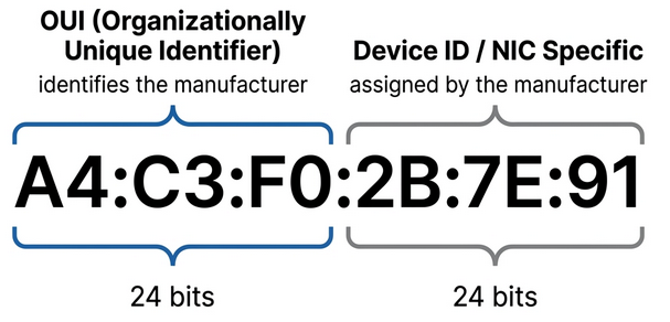
A MAC address (Media Access Control) is a 48-bit hardware address burned into every network interface. It’s globally unique.
A4:C3:F0:2B:7E:91── ── ── ── ── ── \__OUI__/ \__Device__/
First 3 octets = OUI (Organizationally Unique Identifier) Assigned to the manufacturer by IEEELast 3 octets = Device ID (assigned by manufacturer, unique per NIC)# View your MAC addressip link show eth0# link/ether a4:c3:f0:2b:7e:91 brd ff:ff:ff:ff:ff:ff
# Look up a MAC address OUI (manufacturer)# First 3 octets identify the vendor# https://maclookup.app/ or:curl -s "https://api.maclookup.app/v2/macs/A4C3F0" | python3 -m json.toolUnicast, Multicast, and Broadcast
Section titled “Unicast, Multicast, and Broadcast”| Type | Destination | Who receives it |
|---|---|---|
| Unicast | One specific MAC address | Only the target device |
| Multicast | A group MAC address | All devices in the multicast group |
| Broadcast | FF:FF:FF:FF:FF:FF | Every device on the LAN segment |
The least significant bit of the first octet determines the type:
- Bit = 0 -> unicast (destined for a single device)
- Bit = 1 -> multicast (destined for a group)
Ethernet Frame Structure
Section titled “Ethernet Frame Structure”Every piece of data on an Ethernet network is wrapped in a frame with this structure:
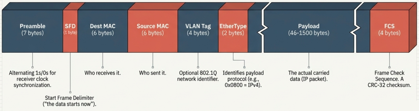
| Field | Size | Purpose |
|---|---|---|
| Preamble | 7 bytes | Alternating 1s and 0s - lets the receiver sync its clock |
| SFD (Start Frame Delimiter) | 1 byte | Signals: “the actual frame data starts now” |
| Destination MAC | 6 bytes | Who should receive this frame |
| Source MAC | 6 bytes | Who sent this frame |
| VLAN tag (optional) | 4 bytes | Identifies which VLAN the frame belongs to (802.1Q) |
| EtherType | 2 bytes | What protocol is in the payload (e.g., 0x0800 = IPv4, 0x86DD = IPv6) |
| Payload | 46-1500 bytes | The actual data (IP packet, ARP request, etc.) |
| FCS (Frame Check Sequence) | 4 bytes | CRC-32 checksum for error detection |
VLANs - Virtual LANs
Section titled “VLANs - Virtual LANs”A VLAN lets you create multiple logical networks on the same physical switch. Devices on VLAN 10 can’t see traffic on VLAN 20, even if they’re plugged into the same switch.
- 802.1Q tag is inserted into the Ethernet frame header (4 bytes) to identify which VLAN a frame belongs to
- Traffic between VLANs requires a router (inter-VLAN routing)
- Common use: separate guest Wi-Fi (VLAN 100) from corporate network (VLAN 10) on the same physical infrastructure
Trunks, routing between VLANs, and the cloud-scale alternative, VXLAN, are in VLANs and overlays.
# Check VLAN configuration on Linuxip -d link show
# Create a VLAN interfacesudo ip link add link eth0 name eth0.10 type vlan id 10sudo ip addr add 192.168.10.1/24 dev eth0.10sudo ip link set eth0.10 up
# View VLAN membership on a managed switch (varies by vendor)# Cisco: show vlan brief# Linux bridge: bridge vlan show
How a Frame Travels Through the Network
Section titled “How a Frame Travels Through the Network”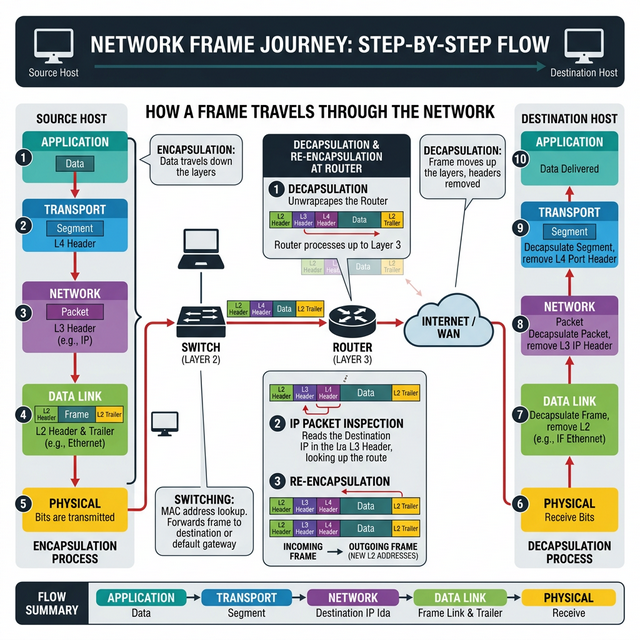
Putting it all together - when you browse example.com:
- Application layer generates an HTTP request
- Transport layer wraps it in a TCP segment (adds port numbers)
- Network layer wraps it in an IP packet (adds source/destination IP)
- Data link layer wraps it in an Ethernet frame (adds source/destination MAC)
- Physical layer converts the frame to electrical signals and pushes it onto the wire
- At each router hop, the Ethernet frame is unwrapped and rewrapped with new MAC addresses, but the IP packet inside stays the same until it reaches the destination network
Encapsulation across the stack
Section titled “Encapsulation across the stack”Each layer treats what it receives from above as opaque payload and prepends its own header. The Ethernet layer also appends a trailer with the frame check sequence. The result is a set of nested envelopes, and the unit of data has a different name at each layer.
| Ethernet header | IP header | TCP header | HTTP request | FCS ||<-- link ------->|<-- network ->|<-- transport -->|<-- application -->|| Layer | Unit | Header carries | Implemented by |
|---|---|---|---|
| Application | Message | Protocol-specific fields (method, status, record type) | Hosts |
| Transport | Segment (TCP) or datagram (UDP) | Ports, sequence and acknowledgment numbers | Hosts |
| Network | Packet (datagram) | Source and destination IP, TTL, protocol | Hosts and routers |
| Data link | Frame | Source and destination MAC, frame check sequence | Hosts, switches, routers (each hop) |
| Physical | Bits | None | Every device |
The table also shows how far up the stack each device looks. A host implements all five layers. A router stops at layer 3: it rebuilds the frame on every hop but never reads the TCP header. A layer 2 switch stops at layer 2. This is why a switch can’t make routing decisions and a router can’t see ports (a firewall or load balancer that does is working above its layer).
tcpdump can print the nested headers directly. The -e flag adds the Ethernet header to the usual IP and TCP output.
sudo tcpdump -e -nn -c 1 -i eth0 'tcp port 443'
# Expected output (abbreviated):# 10:42:07.118 aa:bb:cc:dd:ee:01 > aa:bb:cc:dd:ee:02, ethertype IPv4 (0x0800), length 74:#   10.0.1.15.51832 > 203.0.113.10.443: Flags [S], seq 1021876, win 64240, length 0#   ^ link layer (MAC)      ^ network layer (IP)   ^ transport layer (TCP port)
Layering has a cost as well as a benefit.
- Modularity - Swap Wi-Fi for fiber and HTTP never notices. Each layer has one job and a defined interface.
- Duplicated work - Both the link layer and TCP detect errors, and TCP still has to, because a switch can corrupt a frame after the link check passes.
- Hidden information - A layer can’t see what the others know. Application code can’t tell why a connection is slow, and a router can’t tell what the application cares about.
Packet switching
Section titled “Packet switching”A host breaks a long message into chunks and wraps each in a header, producing packets. Routers and switches then move packets toward the destination one hop at a time. The complete chain of links and switches a packet crosses is its path.
Store-and-forward
Section titled “Store-and-forward”A switch has to receive an entire packet before it can send the first bit onward. Sending a packet of L bits over a link of R bits per second takes L / R seconds, and that delay repeats on every link along the path.
delay over N links of equal rate = N x (L / R)
Example: 1500 bytes = 12,000 bits, 3 links at 100 Mbit/s         3 x (12,000 / 100,000,000) = 0.36 ms
Each outgoing link has an output queue. If packets arrive faster than the link can send them, they wait in the queue. If the queue is full, the next arriving packet is dropped. Loss and queuing delay are therefore the normal signs of a congested link, not signs of a fault.
Forwarding and routing
Section titled “Forwarding and routing”Two jobs happen on every router, on very different timescales:
- Forwarding - the per-packet decision. The router looks up the destination IP in its forwarding table and sends the packet out the matching interface.
- Routing - the network-wide computation that fills those forwarding tables. Routing protocols run in the background and update the tables when links change.
See Forwarding and routing for the full comparison and Inside a router for the hardware view.
Packet switching vs circuit switching
Section titled “Packet switching vs circuit switching”The classic telephone network reserved capacity end to end for the duration of a call. The internet shares capacity packet by packet.
| Circuit switching | Packet switching | |
|---|---|---|
| Capacity | Reserved per connection (a time slot or frequency band) | Shared on demand |
| Setup | Signaling before data flows | None |
| Idle time | Reserved capacity is wasted | Others use the idle capacity |
| Overload | New connections are refused | Queues grow, then packets drop |
| Used by | Traditional voice networks | The internet |
Bursty traffic is why packet switching wins. Take a 1 Gbit/s link where each active user needs 100 Mbit/s but is active only 5% of the time. Circuit switching reserves capacity for each user, so it serves 10. With packet switching, 60 users can share the link: the chance that more than 10 are active at once is about 0.02%, so queues rarely build up. This is statistical multiplexing, and it is the economic basis of shared networks, including cloud networks.
Delay, loss, and throughput
Section titled “Delay, loss, and throughput”The time a packet needs to cross one node is the sum of four delays:
d_nodal = d_proc + d_queue + d_trans + d_prop| Delay | What it is | Depends on | Typical size |
|---|---|---|---|
| Processing | Reading the header, choosing the output link, checking errors | Router hardware | Microseconds |
| Queuing | Waiting in the output queue | Traffic load | Microseconds to many milliseconds, varies |
| Transmission | Pushing all bits onto the link: L / R | Packet size and link rate | Microseconds on fast links |
| Propagation | A bit crossing the medium: d / s | Distance and medium (about 2 x 10^8 m/s in fiber or copper) | About 5 ms per 1,000 km |
Transmission and propagation get mixed up often. Transmission delay depends only on packet size and link rate. Propagation delay depends only on distance. Upgrading a link from 1 Gbit/s to 10 Gbit/s shrinks the first and does nothing for the second, which is why a faster link can’t fix latency between continents.
Queuing and traffic intensity
Section titled “Queuing and traffic intensity”Queuing delay is the only variable component. It depends on traffic intensity, the ratio of arriving bits to the link’s capacity:
traffic intensity = (L x a) / R L = average packet size in bits, a = packets arriving per second, R = link rate in bit/s- Below 1 - queues stay short while intensity is low. As it nears 1, delay climbs steeply, not gradually.
- Above 1 - bits arrive faster than they leave. The queue grows until the buffer fills and packets drop.
In practice, a link at 90% utilization already shows latency spikes. If ping latency climbs only while a large transfer is running, the delay is in a queue on the path. See Bufferbloat for the fix.
Throughput
Section titled “Throughput”Throughput is the rate at which data actually arrives at the receiver. It differs from bandwidth, which is the link’s capacity. For a path of several links in series, throughput can’t exceed the slowest one:
throughput = min(R1, R2, ..., RN)For a single transfer, that slowest link is nearly always the access link at either end. The core is heavily over-provisioned. It becomes the bottleneck only when many flows share one link, each getting R / M for M flows.
# Measure achievable throughput between two hostsiperf3 -s                    # on the serveriperf3 -c 10.0.1.20 -t 10    # on the client; reports bandwidth per interval
# Per-hop latency along the pathmtr --report --report-cycles 10 app.example.com
Design principles: narrow waist and end-to-end
Section titled “Design principles: narrow waist and end-to-end”Many protocols sit above IP and many link technologies sit below it, but only one protocol sits at layer 3.
HTTP SMTP DNS QUIC SSH ... (many application protocols) TCP UDP (two main transport protocols) IP (one network protocol: the waist) Ethernet Wi-Fi cellular fiber (many link technologies)Any application that speaks IP can run over any network that carries IP. New applications don’t need new routers, and new link technologies don’t need new applications. That single required protocol is why the internet absorbed Wi-Fi, 5G, and virtual networks without redesign.
The same thinking puts intelligence at the edges. Reliability is the standard example. Even if every hop retransmits lost frames, a router can still crash with a packet in its queue, so only the endpoints can confirm that data arrived intact. TCP does that check end to end. Link-layer retransmission, as in Wi-Fi, is only a performance optimization on top.
NAT, firewalls, and deep packet inspection strain this model, because they rewrite or inspect ports and payloads inside the network. They exist for good operational reasons (conserving IPv4 addresses, filtering threats), but they are why a protocol change like QUIC has to be designed around middleboxes that expect TCP.