The Network Layer
IPv4 Addressing
Section titled “IPv4 Addressing”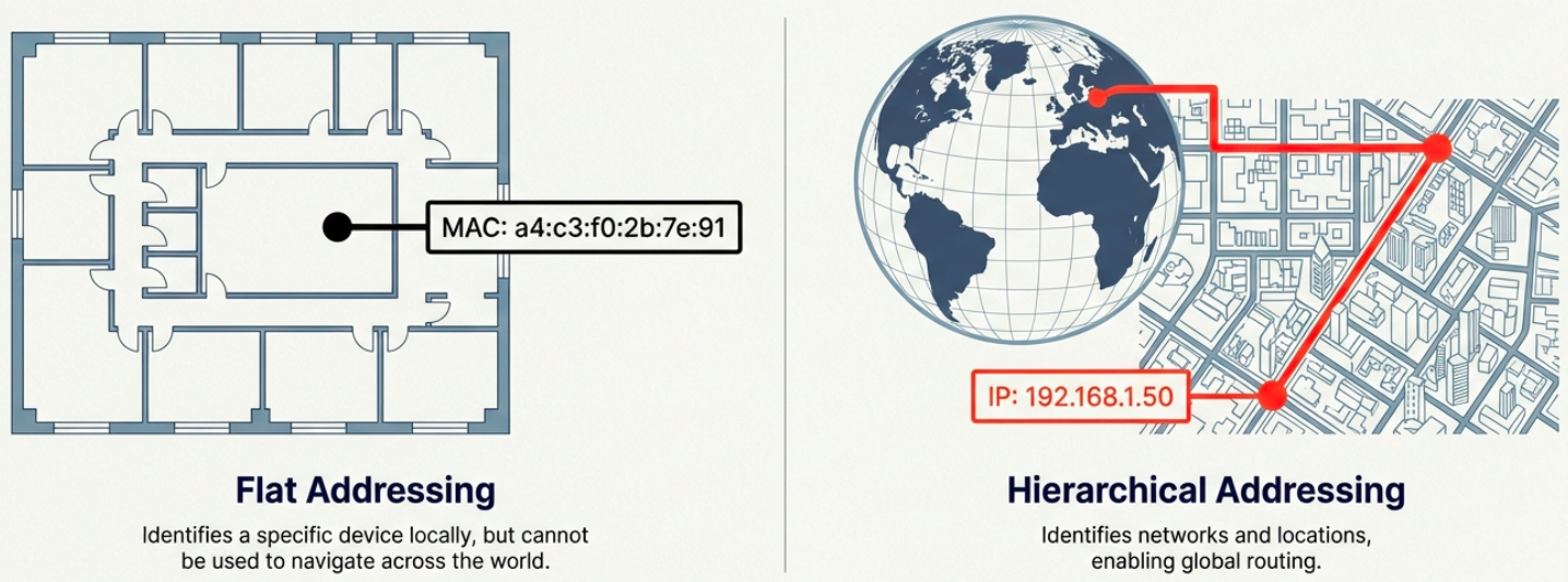
On a LAN, devices communicate using MAC addresses (Layer 2). But MAC addresses are flat - they aren’t hierarchical and can’t be used for routing across networks. IP addresses solve this.
IPv4 Address Format
Section titled “IPv4 Address Format”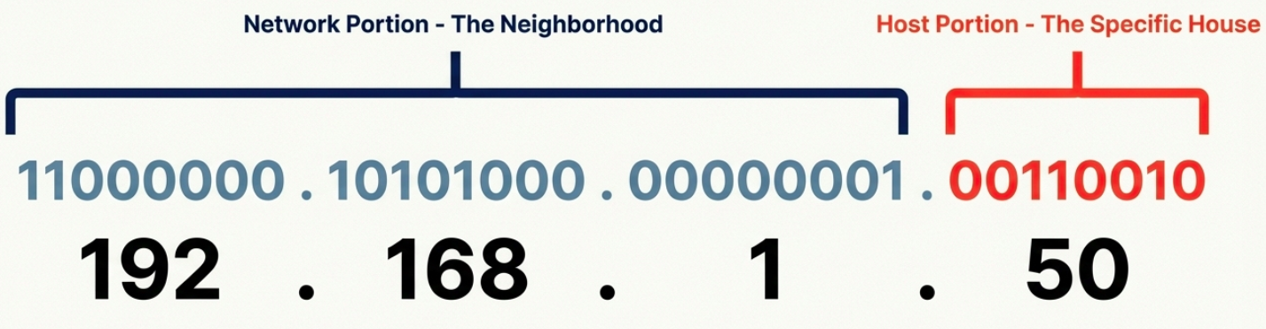
An IPv4 address is a 32-bit number written as four octets in dotted decimal notation:
192.168.1.100 │    │  │  │ 8   8  8  8  bits = 32 bits total
Each octet = 8 bits = 0 to 255- IP addresses belong to networks, not devices. A laptop gets a new IP when it joins a new network.
- Dynamic IP (via DHCP) - automatically assigned, common for clients
- Static IP - manually configured, used for servers and network equipment
- An address belongs to an interface, so a router with four links has four addresses. A subnet is a group of interfaces that reach each other without passing through a router.
This page covers IPv4. IPv6 has its own page: IPv6.
IPv4 Datagram Structure
Section titled “IPv4 Datagram Structure”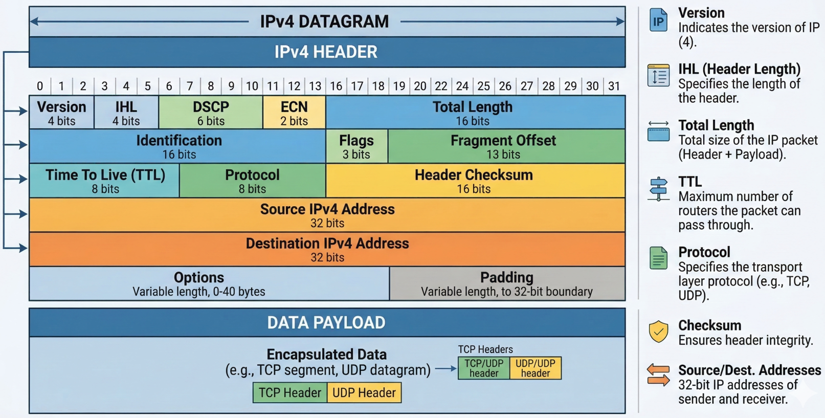
Every IP packet (called a datagram) has a header with these fields:
| Field | Size | Purpose |
|---|---|---|
| Version | 4 bits | IP version (4 for IPv4) |
| Header Length (IHL) | 4 bits | Header size (usually 20 bytes / 5 words) |
| Type of Service (DSCP) | 8 bits | Quality of Service (QoS) priority marking |
| Total Length | 16 bits | Entire datagram size (max 65,535 bytes) |
| Identification | 16 bits | Groups fragments of the same original datagram |
| Flags | 3 bits | Controls fragmentation (DF = Don’t Fragment, MF = More Fragments) |
| Fragment Offset | 13 bits | Position of this fragment in the original datagram |
| TTL (Time to Live) | 8 bits | Hop counter - decremented at each router, dropped at 0 |
| Protocol | 8 bits | Upper-layer protocol (6=TCP, 17=UDP, 1=ICMP) |
| Header Checksum | 16 bits | Error detection for the header only |
| Source IP | 32 bits | Sender’s IP address |
| Destination IP | 32 bits | Recipient’s IP address |
| Options | Variable | Optional - used for testing/debugging (rarely used) |
| Padding | Variable | Zeros to ensure header aligns to 32-bit boundary |
A header with no options is 20 bytes. With a 20-byte TCP header on top, every segment carries at least 40 bytes of overhead before any application data. Because TTL changes at every hop, each router also recomputes the header checksum. IPv6 dropped the checksum for this reason (see IPv6).
The 8-bit DSCP/ToS byte also carries two ECN bits. See QoS and traffic shaping for DSCP and TCP congestion control for ECN.
Fragmentation occurs when a datagram exceeds the MTU (Maximum Transmission Unit) of a link (typically 1500 bytes for Ethernet). The IP layer splits it into smaller fragments, each with the same Identification field. The receiving host reassembles them.
# Check the MTU of an interfaceip link show eth0 | grep mtu# mtu 1500
# Test path MTU to a destination (avoid fragmentation issues)ping -c 4 -s 1472 -M do 8.8.8.8# -s 1472 + 28 bytes overhead = 1500 (exact MTU)# If fragmentation needed, you'll get an ICMP error
Fragmentation example
Section titled “Fragmentation example”Take a 4,000-byte datagram (20-byte header plus 3,980 bytes of payload) that must cross a link with a 1,500-byte MTU. Each fragment can carry at most 1,480 bytes of payload, because 1,500 minus the 20-byte header leaves 1,480. That is a multiple of 8, which matters because the Fragment Offset field counts in 8-byte units.
| Fragment | Payload | Total length | Offset field | MF flag |
|---|---|---|---|---|
| 1 | 1,480 bytes | 1,500 | 0 | 1 |
| 2 | 1,480 bytes | 1,500 | 185 (1,480 / 8) | 1 |
| 3 | 1,020 bytes | 1,040 | 370 (2,960 / 8) | 0 |
All three share the same Identification value. The destination uses it, the offsets, and the MF flag (0 on the last fragment) to reassemble the original. Intermediate routers never reassemble.
Fragmentation is expensive in practice:
- One lost fragment loses the whole datagram. The sender retransmits all of it.
- Many firewalls and NAT devices drop fragments, because only the first one carries the TCP or UDP header they need to match.
- Most TCP traffic sets the DF flag and relies on path MTU discovery instead. A router that cannot forward a DF packet drops it and returns ICMP type 3 code 4 (“fragmentation needed”). The sender then lowers its packet size.
That last mechanism breaks when a firewall drops ICMP. The symptom is a connection that completes the handshake and then hangs on the first large response, while small requests work. Tunnels make it more likely, since each one shrinks the usable MTU (VXLAN takes 50 bytes, WireGuard typically leaves 1,420).
# Find the path MTU hop by hoptracepath -n app.example.com# 1?: [LOCALHOST]                      pmtu 1500# 1:  10.0.1.1                         0.4ms# 2:  203.0.113.9                      1.1ms pmtu 1400
# Work around a black hole by clamping the TCP MSS on the forwarding hostsudo iptables -t mangle -A FORWARD -p tcp --tcp-flags SYN,RST SYN \  -j TCPMSS --clamp-mss-to-pmtu
IPv4 Address Classes (Historical)
Section titled “IPv4 Address Classes (Historical)”Before CIDR, IP addresses were divided into classes based on the first few bits:
| Class | First Bits | Network / Host Split | Range | Hosts per Network | Use |
|---|---|---|---|---|---|
| A | 0 | 8 / 24 | 0.0.0.0 - 127.255.255.255 | 16,777,214 | Large ISPs, governments |
| B | 10 | 16 / 16 | 128.0.0.0 - 191.255.255.255 | 65,534 | Medium-large organizations |
| C | 110 | 24 / 8 | 192.0.0.0 - 223.255.255.255 | 254 | Small networks |
| D | 1110 | N/A | 224.0.0.0 - 239.255.255.255 | N/A | Multicast |
| E | 1111 | N/A | 240.0.0.0 - 255.255.255.255 | N/A | Reserved / experimental |
ARP - Address Resolution Protocol
Section titled “ARP - Address Resolution Protocol”ARP bridges Layer 2 and Layer 3. When a device knows the destination IP (Layer 3) but not the MAC address (Layer 2), it uses ARP to find it.
How ARP works:
- Device broadcasts an ARP request: “Who has IP
192.168.1.1? Tell192.168.1.50” - The device with that IP responds with an ARP reply: “I’m
192.168.1.1, my MAC isa4:c3:f0:2b:7e:91” - The requesting device caches this in its ARP table (entries expire after a timeout to account for network changes)
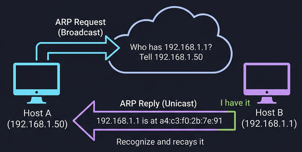
# View the ARP tableip neigh show# or the legacy command:arp -a
# Manually add a static ARP entry (rarely needed)sudo ip neigh add 192.168.1.1 lladdr aa:bb:cc:dd:ee:ff dev eth0
# Clear the ARP cachesudo ip neigh flush all
# On Windowsarp -aSubnetting
Section titled “Subnetting”Why Subnets?
Section titled “Why Subnets?”Before modern routing, IPs were handed out in rigid classes (A,B,C). It was massively wasteful; a company needing 300 addresses would get a Class B with 65,534 hosts, wasting over 65,000 addresses. Subnetting solves this by splitting a large network into smaller, manageable pieces, each with its own gateway router.
Internet │ Core Router ┌────┼────┐ │ │ │ Subnet Subnet Subnet /26 /26 /26 (62) (62) (62) hosts eachSubnet Masks
Section titled “Subnet Masks”A subnet mask is a 32-bit number that tells you where the network/subnet portion ends and the host portion begins:
| Subnet Mask | Binary | CIDR | Network Bits | Host Bits | Usable Hosts |
|---|---|---|---|---|---|
255.0.0.0 | 11111111.00000000.00000000.00000000 | /8 | 8 | 24 | 16,777,214 |
255.255.0.0 | 11111111.11111111.00000000.00000000 | /16 | 16 | 16 | 65,534 |
255.255.255.0 | 11111111.11111111.11111111.00000000 | /24 | 24 | 8 | 254 |
255.255.255.128 | 11111111.11111111.11111111.10000000 | /25 | 25 | 7 | 126 |
255.255.255.192 | 11111111.11111111.11111111.11000000 | /26 | 26 | 6 | 62 |
255.255.255.224 | 11111111.11111111.11111111.11100000 | /27 | 27 | 5 | 30 |
255.255.255.240 | 11111111.11111111.11111111.11110000 | /28 | 28 | 4 | 14 |
255.255.255.252 | 11111111.11111111.11111111.11111100 | /30 | 30 | 2 | 2 |
Calculating Subnets
Section titled “Calculating Subnets”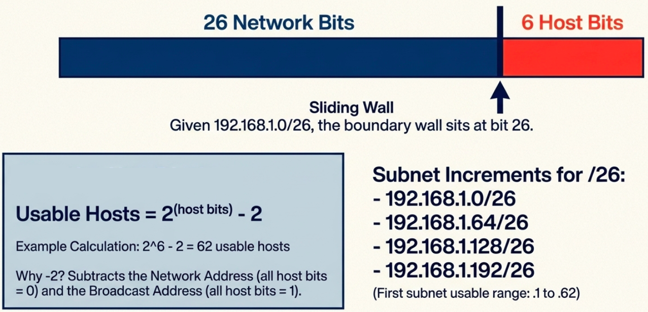
Given 192.168.1.0/26:
- Network bits = 26, Host bits = 6
- Subnet increment = 2^6 = 64
- Subnets:
192.168.1.0/26,192.168.1.64/26,192.168.1.128/26,192.168.1.192/26 - First subnet usable range:
192.168.1.1to192.168.1.62(broadcast:192.168.1.63)
# Quick subnet calculation with ipcalcipcalc 192.168.1.0/26# Network:   192.168.1.0/26# Netmask:   255.255.255.192 = 26# Wildcard:  0.0.0.63# HostMin:   192.168.1.1# HostMax:   192.168.1.62# Broadcast: 192.168.1.63# Hosts/Net: 62
# View your subnet informationip addr show eth0# inet 192.168.1.50/24 brd 192.168.1.255 scope global eth0
CIDR - Classless Inter-Domain Routing
Section titled “CIDR - Classless Inter-Domain Routing”The Problem CIDR Solves
Section titled “The Problem CIDR Solves”Classful addressing was wasteful. A company needing 300 IPs couldn’t use a /24 (254 hosts) and had to request a /16 (65,534 hosts) - wasting 65,000+ addresses. CIDR removed the fixed class boundaries.
How CIDR Works
Section titled “How CIDR Works”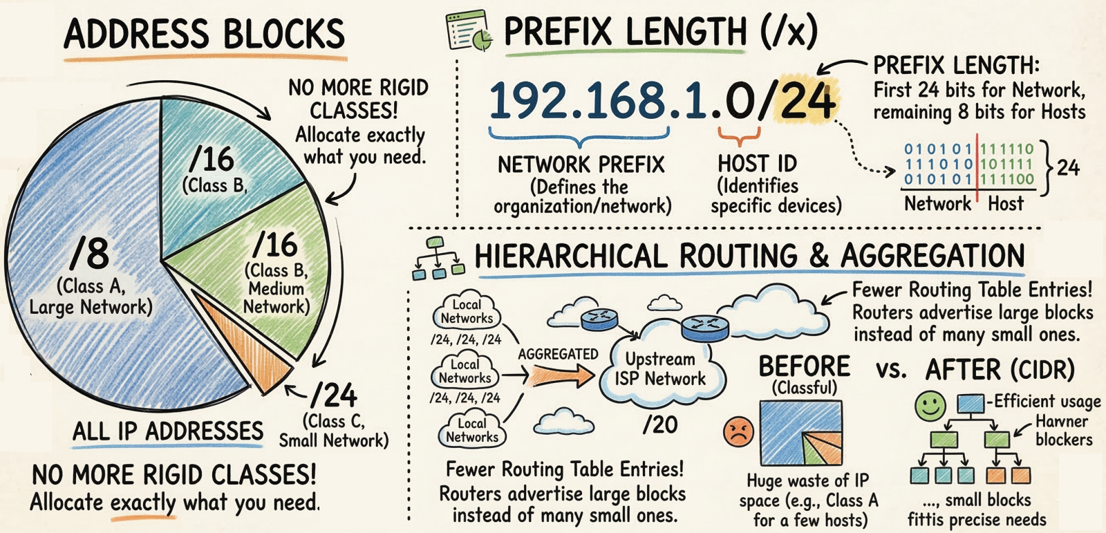
CIDR uses Variable Length Subnet Masking (VLSM) - the network/host boundary can be placed anywhere in the 32 bits, not just at the 8/16/24-bit boundaries.
Classful:  Class A = /8  Class B = /16      Only 3 options  Class C = /24
CIDR:  /1, /2, /3 ... /30, /31, /32    Any prefix length
Key benefits:
- No address waste - allocate exactly the number of IPs needed (e.g., /27 for 30 hosts)
- Route aggregation (supernetting) - combine multiple networks into one route entry (e.g., two /24s become one /23), shrinking routing tables
- Flexible network design - networks can be any size, not just A/B/C
CIDR Quick Reference
Section titled “CIDR Quick Reference”| CIDR | Subnet Mask | Total IPs | Usable Hosts |
|---|---|---|---|
| /8 | 255.0.0.0 | 16,777,216 | 16,777,214 |
| /16 | 255.255.0.0 | 65,536 | 65,534 |
| /20 | 255.255.240.0 | 4,096 | 4,094 |
| /24 | 255.255.255.0 | 256 | 254 |
| /25 | 255.255.255.128 | 128 | 126 |
| /26 | 255.255.255.192 | 64 | 62 |
| /27 | 255.255.255.224 | 32 | 30 |
| /28 | 255.255.255.240 | 16 | 14 |
| /30 | 255.255.255.252 | 4 | 2 |
| /32 | 255.255.255.255 | 1 | 1 |
Forwarding and routing
Section titled “Forwarding and routing”The network layer is split into two parts that run on different timescales. The short version is in Introduction to networking. This is the full comparison.
| Forwarding (data plane) | Routing (control plane) | |
|---|---|---|
| Scope | One router, one packet | The whole network |
| Job | Move a packet from an input port to the right output port | Compute paths and fill the forwarding tables |
| Timescale | Nanoseconds per packet | Milliseconds to seconds, after a topology change |
| Runs on | Hardware: line cards, ASICs, TCAM | Software: the router’s CPU, or a remote controller |
| Linux view | The kernel forwarding path (net.ipv4.ip_forward=1) | A routing daemon such as FRR or BIRD, or static routes |
In a traditional network every router runs its own control plane and exchanges messages (OSPF, BGP) with its neighbors. In software-defined networking the control plane moves to a logically centralized controller that pushes forwarding rules to simple switches. Cloud VPC route tables work this way: you edit a central table, and the provider’s controller programs the data plane.
The service model: best effort
Section titled “The service model: best effort”IP promises nothing about a packet once it leaves the sender:
- It may be dropped when a queue fills.
- It may arrive out of order.
- Delay is not bounded and bandwidth is not reserved.
This looks like a weakness but it is the reason the internet scales. The network core stays simple, and the end hosts supply what they need: TCP adds reliability and ordering, and adaptive applications (see CDNs and video streaming) adjust to whatever bandwidth they get. Operators then add capacity and, where it matters, differentiated treatment with DSCP (see QoS and traffic shaping).
Routing
Section titled “Routing”How Routing Works
Section titled “How Routing Works”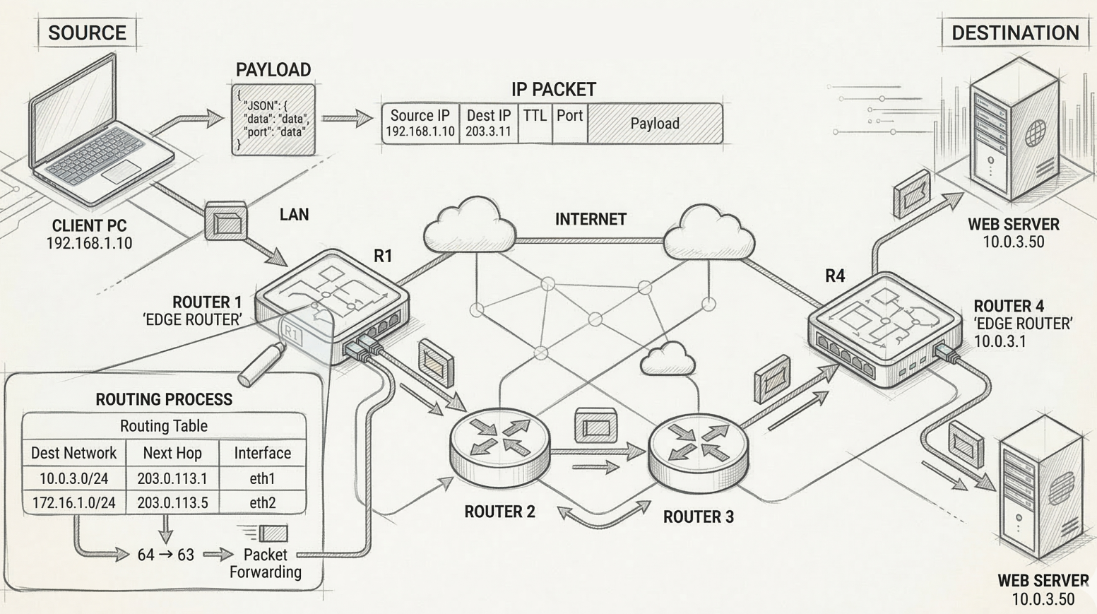
A router sits between networks and decides where to forward each packet based on its destination IP:
- Packet arrives on one interface
- Router reads the destination IP from the IP header
- Router looks up the destination in its routing table
- Router forwards the packet out the interface closest to the destination
The Routing Table
Section titled “The Routing Table”Every router maintains a routing table with these core columns:
| Column | What it contains |
|---|---|
| Destination Network | Network ID + subnet mask (CIDR notation) |
| Next Hop | IP of the next router to forward to (or “directly connected”) |
| Metric | Cost/distance of this route (lower = preferred) |
| Interface | Which of the router’s interfaces to send the packet out of |
# View the routing table on Linuxip route show# default via 192.168.1.1 dev eth0 proto dhcp metric 100# 192.168.1.0/24 dev eth0 proto kernel scope link src 192.168.1.50
# Add a static routesudo ip route add 10.0.0.0/8 via 192.168.1.254
# Windowsroute print
Longest-prefix match
Section titled “Longest-prefix match”A destination often matches several routes. The router picks the one with the longest prefix, meaning the most specific match. The default route (0.0.0.0/0) matches everything and is used only when nothing else does.
| Route | Next hop |
|---|---|
10.0.0.0/8 | 10.255.0.1 |
10.1.0.0/16 | 10.255.0.2 |
10.1.2.0/24 | 10.255.0.3 |
0.0.0.0/0 | 192.0.2.1 |
A packet for 10.1.2.77 matches the first three routes, and the /24 wins. A packet for 10.1.9.1 matches the /8 and /16, so the /16 wins. A packet for 203.0.113.5 matches only the default route. The order of entries in the table does not matter.
# Ask the kernel which route a destination would useip route get 10.1.2.77# 10.1.2.77 via 10.255.0.3 dev eth1 src 10.255.0.10 uid 1000This rule is what makes route aggregation work. A provider holding 198.51.96.0/20 can advertise that single prefix for eight customer /23 blocks, so the rest of the internet needs one entry instead of eight. If the customer with 198.51.100.0/23 moves to another provider and keeps its addresses, the new provider advertises that /23 as well. Routers now see both the /20 and the /23, and the longer one pulls the customer’s traffic to the new provider. See Supernetting for the aggregation arithmetic.
Routing Protocols
Section titled “Routing Protocols”Routers don’t know about every network by default - they learn routes dynamically by talking to neighboring routers using routing protocols.
This section is the overview. Routing protocols covers how link state and distance vector work, OSPF adjacencies and areas, and BGP route selection and policy.
Interior Gateway Protocols (IGP) - Within an Autonomous System
Section titled “Interior Gateway Protocols (IGP) - Within an Autonomous System”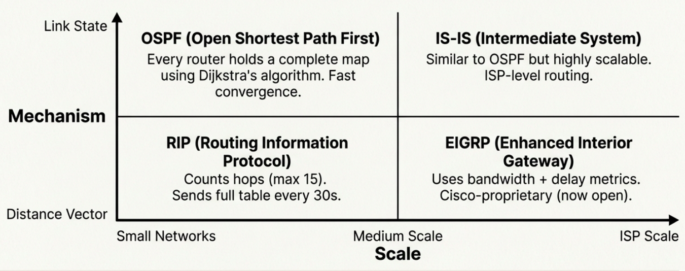
| Protocol | Type | How it works | Scale |
|---|---|---|---|
| RIP (Routing Information Protocol) | Distance vector | Counts hops (max 15). Sends full routing table to neighbors every 30s. | Small networks (fewer than 100 routers) |
| EIGRP (Enhanced Interior Gateway) | Advanced distance vector | Uses bandwidth + delay as metrics. Cisco-proprietary (now open). | Medium networks |
| OSPF (Open Shortest Path First) | Link state | Every router has a complete map of the network. Uses Dijkstra’s algorithm. | Large enterprise networks |
| IS-IS (Intermediate System) | Link state | Similar to OSPF. Used by ISPs and very large networks. | ISP-scale networks |
Distance vector protocols are simpler but slower to converge. Routers only know what their neighbors tell them (“I can reach 10.0.0.0 in 3 hops”).
Link state protocols are more complex but converge faster. Every router has the full topology map and independently calculates the best path.
Exterior Gateway Protocol (EGP) - Between Autonomous Systems
Section titled “Exterior Gateway Protocol (EGP) - Between Autonomous Systems”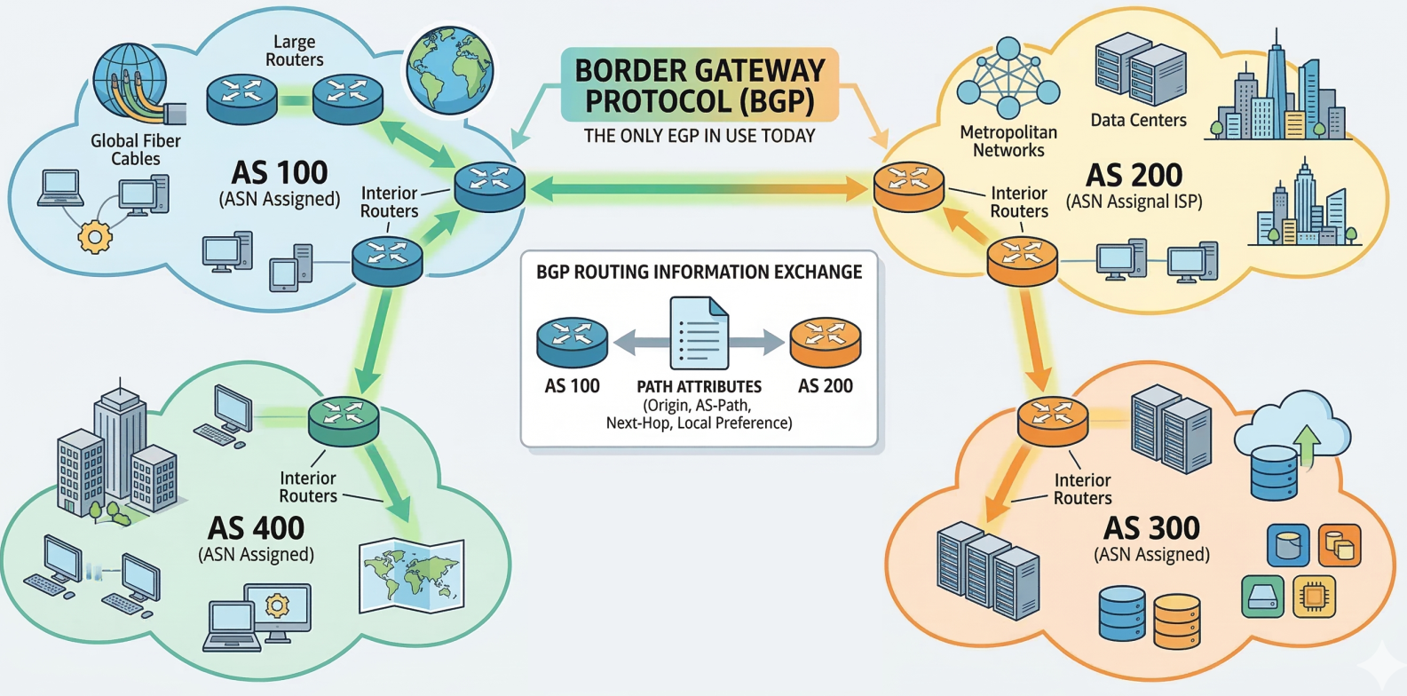
BGP (Border Gateway Protocol) is the only EGP in use today. It’s the protocol that makes the internet work - every ISP, cloud provider, and large organization uses BGP to exchange routing information.
- An Autonomous System (AS) is a collection of networks under one administrative entity
- Each AS gets an ASN (Autonomous System Number) assigned by IANA/regional registries
- BGP routers exchange path attributes to determine the best route across the internet
Inside a router
Section titled “Inside a router”A router has four parts. Three of them make up the data plane and run in hardware. The fourth is the control plane and runs in software.
flowchart LR
    subgraph DP["Data plane (hardware)"]
        I1["Input port 1<br/>lookup, TTL-1"] --> F{"Switching<br/>fabric"}
        I2["Input port 2"] --> F
        F --> O1["Output port 1<br/>queue, scheduler"]
        F --> O2["Output port 2"]
    end
    RP["Routing processor<br/>OSPF, BGP, route table"] -.->|"forwarding table copy"| I1
    RP -.-> I2
The hardware is needed because of the time budget. A 100 Gbit/s link delivering 64-byte packets leaves about 5 ns per packet (512 bits / 100 Gbit/s = 5.12 ns). A CPU lookup cannot keep up.
| Part | What it does |
|---|---|
| Input port | Terminates the link, decapsulates the frame, then looks up the destination in a local copy of the forwarding table. Hardware does the longest-prefix match in TCAM, memory that compares an address against all entries in one cycle. It also decrements the TTL and updates the header checksum |
| Switching fabric | Moves the packet from the input port to the chosen output port |
| Output port | Buffers packets waiting for the link, runs the scheduler and drop policy, then frames and transmits them |
| Routing processor | Runs the routing protocols, maintains the routing table, computes the forwarding table, and handles control traffic and management |
Each input port keeps its own copy of the forwarding table so a lookup never waits on the routing processor. The routing table (the RIB) holds every route learned. The forwarding table (the FIB) holds the best route per prefix, in a form the hardware can search. On Linux, ip route shows the FIB.
Switching fabrics
Section titled “Switching fabrics”| Fabric | How it works | Limit |
|---|---|---|
| Memory | The CPU copies each packet into memory, looks it up, and copies it out. This is how early routers and software routers work | Throughput is under half the memory bandwidth, and one packet moves at a time |
| Bus | The input port tags the packet with its output port and sends it over a shared bus | One packet crosses at a time, so speed is capped by the bus |
| Crossbar or multistage | A grid of buses with switchable crosspoints, so many non-conflicting transfers happen in parallel | Two packets for the same output port still have to take turns |
If packets queue at an input port because the fabric is busy, the packet at the head can block those behind it even when their output ports are free. This is head-of-line blocking. With simple FIFO input queues it caps throughput at roughly 58% of line rate under uniform traffic, which is why high-end routers queue at the output and use faster fabrics. Output queueing, schedulers, and buffer sizing are covered in QoS and traffic shaping.
Going deeper: Router switching and queueing covers the packet time budget, fabric designs, head-of-line blocking, and where buffer sizing rules come from.
Why this matters when troubleshooting
Section titled “Why this matters when troubleshooting”Most packets are handled entirely in the data plane. Packets addressed to the router itself, such as ping, traceroute replies, and routing protocol messages, are handed to the routing processor, which is slow and rate-limited on purpose.
That explains a common misreading of mtr. If one middle hop shows 40% loss but the final hop shows none, the router is only deprioritizing its own ICMP replies. Traffic through it is fine. Loss that continues to the last hop is real.
Non-Routable (Private) Address Space
Section titled “Non-Routable (Private) Address Space”RFC 1918 reserves three IP ranges for private/internal use. These IPs are never routed on the public internet - IGPs route them internally, but EGPs (BGP) reject them.
| Range | CIDR | Total IPs | Typical Use |
|---|---|---|---|
10.0.0.0 - 10.255.255.255 | 10.0.0.0/8 | 16.7 million | Large enterprise networks, cloud VPCs |
172.16.0.0 - 172.31.255.255 | 172.16.0.0/12 | ~1 million | Medium organizations, Docker default |
192.168.0.0 - 192.168.255.255 | 192.168.0.0/16 | 65,536 | Home networks, small offices |
Devices on private IPs reach the internet through NAT (Network Address Translation), which rewrites the private source IP to the router’s public IP on outgoing packets.
| Routable (Public) IPs | Non-Routable (Private) IPs |
|---|---|
| Forwarded between networks by routers | Not forwarded beyond the local network |
| Globally unique, assigned by RIRs | Can be reused in any private network |
| Directly accessible from the internet | Requires NAT for internet access |
| Needs firewall protection | Inherently isolated from the internet |
Other reserved ranges
Section titled “Other reserved ranges”Several other ranges have fixed meanings. Seeing one on an interface often tells you what went wrong.
| Range | Meaning | What to check when you see it |
|---|---|---|
0.0.0.0/8 | ”This host” or “any address” | A client with 0.0.0.0 as source is mid-DHCP. A server bound to 0.0.0.0:443 listens on every interface |
127.0.0.0/8 | Loopback | Traffic never leaves the host |
169.254.0.0/16 | Link-local | A host holding 169.254.x.x could not reach a DHCP server. Cloud metadata services also live at 169.254.169.254 |
100.64.0.0/10 | Shared address space for carrier-grade NAT | A 100.64.x.x address on your WAN link means your ISP is NATing you, so inbound port forwarding will not work. Overlay VPNs such as Tailscale also use it |
224.0.0.0/4 | Multicast | Used by routing protocols and discovery (OSPF uses 224.0.0.5) |
255.255.255.255 | Limited broadcast | Delivered to every host on the local subnet and never routed |
192.0.2.0/24, 198.51.100.0/24, 203.0.113.0/24 | Documentation | Safe for examples and tests, never routed |
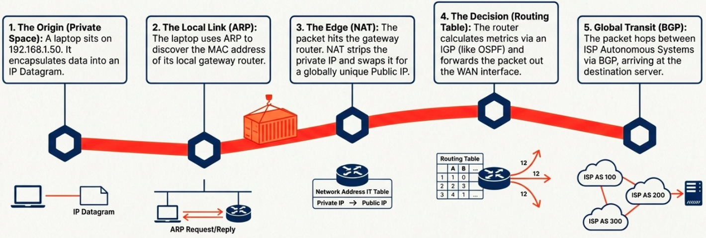
Synthesis: The Complete Path
Section titled “Synthesis: The Complete Path”Layer 3 is an elegant choreography of local discovery, private isolation, and global routing.